The purpose of using the nimbus control is so the ideal flow rate can be achievable for any circulator in your system. Flow rate is important. A boiler circulator running too slowly can overheat, whereas running too quickly can negatively affect stratification in thermal storage tanks by stirring the hot and cold water.
Using the manual dip switch settings on the nimbus, you can test different speeds in order to determine the best flow rate for transferring heat.
The default settings are with all switches in the off position as seen here.
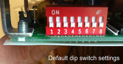
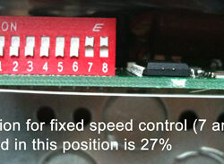
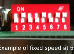
Using the dip switches, you can manually set the controller to a fixed speed. You are able to configure it in one percent increments between 27 and 100 percent output. Please note, we have found most circulators to be unable to work below 40 percent as set on the nimbus control.

Using the Nimbus controller in this manner will give you a single user defined speed for most any circulator. Our personal experience is with using the TACO circulators, 007, 0010, 0014 models.
Using Nimbus for True Variable Speed with NFCS
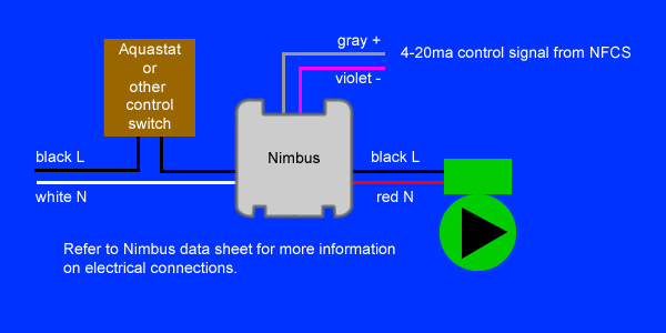
Another way to use the nimbus is with a nofossil control system – (now called VESTA) , NFCS. The analog out(AO), on the left hand column are the four outputs being controlled with 4-20ma control signal.
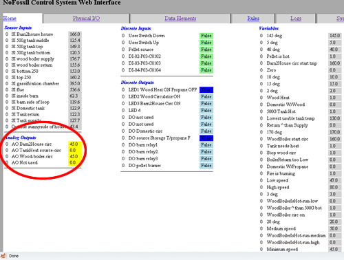
The benefit of using the Nimbus with the NFCS is to drive your circulator speeds dynamically based on current heating system temperatures and rule sets. This allows you to have even greater control over your heating system and also run your system at its optimum settings.
In this setup, the output of the Nimbus control is being controlled by the NFCS via a 4-20ma signal. The NFCS connects directly to each specific nimbus controller with a signal wire coming through a variable speed breakout box.
One of the first things you need to do when setting up your variable speed controller to work with NFCS is to configure the jumper so it will work with 4-20ma signal.
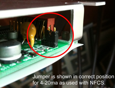
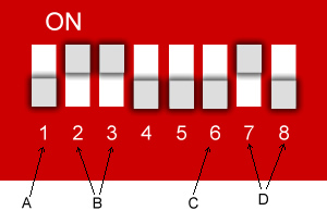
Using the manual we can determine how to best set the Nimbus for our system. This is an example of a configuration, set to run on current control. This example is also to run at 60 percent if no signal is present. Where the manual refers to a “fan”, this applies to the circulator in our scenario.
A. Fan On / Fan Off Feature (switch #1): To turn fan(s) off below the set idle speed (see table 3). Set switch #1 to the ON position. To keep fans running at idle speed below the set idle speed, set switch #1 to the OFF position.
C. Control Signal Loss Options (switch#6): If the control signal is lost, (less than 4mA in I mode, less than 2VDC in V mode) when switch 6 is OFF fans will continue to idle or remain off. To send fans to full speed if the control signal is lost, set switch 6 to the ON position.

In the event that the NFCS is offline and not supplying 4-20ma signals, the nimbus can be configured so that it can either run in one of four preselected idle speeds or simply run wide open assuming that the aquastat or other control switch is supplying line voltage to the nimbus.
